Building a wiring harness for an engine swap is a funny thing. You spend dozens of hours doing it, and nobody will ever really get to admire your work. Once it's done, you don't think about it again unless something goes wrong. Lots of people think it's a really hard thing to design, too, which I find interesting. A little bit of planning goes a long way.
In this case, it's a fairly simple exercise to route between the various sensors required to run the engine, the ECU, and a few ancillary subsystems. Once you're familiar with the basics of EFI (and especially speed-density fuel injection), figuring out how to run wires is pretty simple. I won't get into the specifics of my configuration, as I intend this to be an illustrated guide on construction techniques.
Once you've identified all of the various origin and termination points (for example, battery-to-throttle position sensor, or throttle position sensor-to-ECM), it's a good idea to document things thoroughly. Document which plug and pin serves which function, and decide where the junction plugs will be so you can do things like remove the engine without pulling the wiring harness completely off. Document each wire's color, too. Few modern cars follow such time-honored traditions as making every battery-voltage supply wire red and every ground wire black, and you shouldn't either.
I think I bought something like 55 different color/stripe/gauge combinations from EFI Connection, and it was money very well spent. At any given time during the construction process I could trace a wire with ease and immediately knew the purpose of any wire that wandered away from its route. You can see the worksheet I used to document junction plugs, colors, functions and notes here - it's messy, but it's grown organically over the months. The focus there is on sensor-to-ECM wires. I've also got a map of indirect and support wiring that I've developed over time:
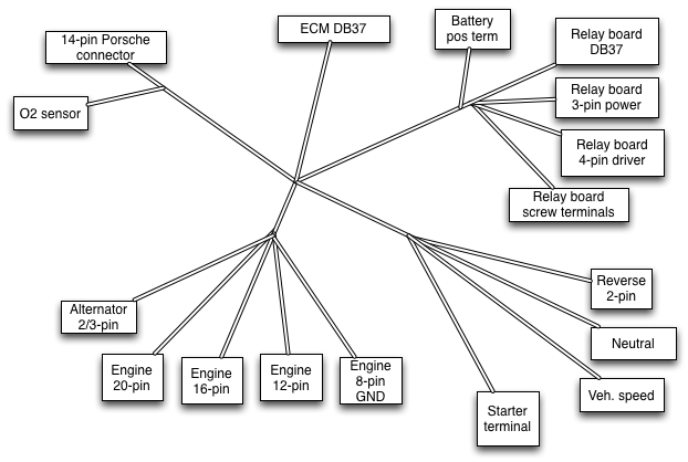
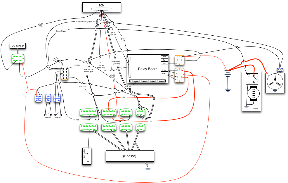 Here you can see the junction plugs, connections between the engine and other systems, etc. It's not 100% complete, but it's for my own reference. Because this diagram is much more functional than it is physical, I also created a diagram showing the various branches I'll need, based on the location of plugs in the engine bay.
As you can imagine, once I'm done, it will be very easy to combine the three documents to end up with something I can use as a reference later on. And I will! The shorthand notes I take will mean nothing in two years or even two months.
Okay, so I've done my planning. What do I need? My shopping list is as follows:
I've laid the wire out in the general flow around the engine or engine bay to estimate lengths, and wrapped bundles with blue painter's tape.
 I've also ordered my plugs, receptacles, pins, and dummy pins. For this build, I've relied very heavily on the Molex MX150L series. They're available from Mouser, they're high quality, and they're sealed. They're also complete overkill, but I only want to do this job once. I've also got a good quality stripper tool, and a cheap crimper that I know how to use well. Consider splurging on tools. Eastern Beaver is an excellent source for tools.
After stripping the wire end according to the Application Specification, I crimp the ends.
 Repeat this a hundred times or so, poking the terminated wires into the plug or receptacle into the positions documented during planning.
For wires that require shielding, I purchased shielded tefzel wire from Aircraft Spruce in the appropriate gauge. This is seriously beefy stuff, and I highly recommend it for applications that are sensitive to noise. For maximum noise protection, you have to ground the shield on one end (not both!). To do that, strip the outermost insulation back, exposing the braid. Pick at the braid in a line until it unravels, and then pull it to one spot, twisting it until it looks like this:
 Trim the twist, and crimp a splice connector on.
 Strip and crimp on your ground wire.
 ...and connect the ground wire to an appropriate location. It's important not to connect both ends of the shield to ground or you can create ground loops where there exists a voltage potential in different places, such as between the engine and the chassis, for example. That will carry noise into the system.
Now that you've terminated your wires, start wrapping the bare wires with 3M Super 33 vinyl electrical tape. Yes, the specific electrical tape matters. Super 33 is rated to 105 degrees Celsius and resistant to corrosive chemicals. As usual, read the datasheet!
Starting with the smallest bunches of wires, begin your wrap a few inches away from the plug, and work your way up toward it, stopping at the distance specified in the plug/receptacle data sheet.
 Slip your split loom onto the wire, with the end of the loom coming halfway up the tape. The loom should be long enough to reach from this point until the nearest y-split in the harness.
 Then continue wrapping to enclose the end of the loom. This is your waterproof seal. As usual, being judicious in your wrapping is beneficial. Stretch the tape according to the instructions in the data sheet, and use only as much as is necessary.
 Start working your way down, continuing to stretch the tape appropriately. You should be able to clearly make out the ridges in the loom, and the tape should overlap half its width. Once you've made it all the way to the nearest y-split, give a couple of wraps around the bigger portion of the harness on either side. This will keep your branch from separating, and will anchor the other ends of the wire.
 In this photo, you can see how I've anchored the branch. Continue working your way around the harness, covering the smaller branches in turn, and then doing the larger.
 Branches should stick out of the split in the larger lengths of loom, and get wrapped similarly on the outside to anchor them where they exit. Always wrap "down" the harness, from the sensor to the ECM. In combination with the method for starting the wrapping inside the loom, that will ensure that you never have any exposed edges of electrical tape. If you do it right, the only tape end that will be exposed will be way down at the ECM plug, which is inside the car.
In this case, it's a fairly simple exercise to route between the various sensors required to run the engine, the ECU, and a few ancillary subsystems. Once you're familiar with the basics of EFI (and especially speed-density fuel injection), figuring out how to run wires is pretty simple. I won't get into the specifics of my configuration, as I intend this to be an illustrated guide on construction techniques.
Once you've identified all of the various origin and termination points (for example, battery-to-throttle position sensor, or throttle position sensor-to-ECM), it's a good idea to document things thoroughly. Document which plug and pin serves which function, and decide where the junction plugs will be so you can do things like remove the engine without pulling the wiring harness completely off. Document each wire's color, too. Few modern cars follow such time-honored traditions as making every battery-voltage supply wire red and every ground wire black, and you shouldn't either.
I think I bought something like 55 different color/stripe/gauge combinations from EFI Connection, and it was money very well spent. At any given time during the construction process I could trace a wire with ease and immediately knew the purpose of any wire that wandered away from its route. You can see the worksheet I used to document junction plugs, colors, functions and notes here - it's messy, but it's grown organically over the months. The focus there is on sensor-to-ECM wires. I've also got a map of indirect and support wiring that I've developed over time:
As you can imagine, once I'm done, it will be very easy to combine the three documents to end up with something I can use as a reference later on. And I will! The shorthand notes I take will mean nothing in two years or even two months.
Okay, so I've done my planning. What do I need? My shopping list is as follows:
- Plug/receptacle pairs
- Pins appropriate to the wire gauge I'm using
- Butt crimp connectors
- Dummy plugs to fill "blanks" in the harness junctions
- Electrical tape
- Fire-resistant split wiring loom
I've laid the wire out in the general flow around the engine or engine bay to estimate lengths, and wrapped bundles with blue painter's tape.

After stripping the wire end according to the Application Specification, I crimp the ends.

For wires that require shielding, I purchased shielded tefzel wire from Aircraft Spruce in the appropriate gauge. This is seriously beefy stuff, and I highly recommend it for applications that are sensitive to noise. For maximum noise protection, you have to ground the shield on one end (not both!). To do that, strip the outermost insulation back, exposing the braid. Pick at the braid in a line until it unravels, and then pull it to one spot, twisting it until it looks like this:


Now that you've terminated your wires, start wrapping the bare wires with 3M Super 33 vinyl electrical tape. Yes, the specific electrical tape matters. Super 33 is rated to 105 degrees Celsius and resistant to corrosive chemicals. As usual, read the datasheet!
Starting with the smallest bunches of wires, begin your wrap a few inches away from the plug, and work your way up toward it, stopping at the distance specified in the plug/receptacle data sheet.


