As part of my ongoing Subaru EZ30 engine installation into my 1974 Porsche 914, I discovered that the stock intake manifold simply won't work. The inlet faces the wrong way (rearward), and cutting a hole for relief would interfere with the engine cover latch.
Unfortunately, unlike the EJ engines, it can't be reversed to face forward, either. The bolt pattern is uniform left-to-right so the intake runners line up okay, but the engine case has some bosses on it that interfere. Grinding those off might work, but there is an oil line that would have to be relocated, as well as figuring out a way to mount the alternator in a way that doesn't interfere with the manifold. As a fun addition, due to the location of the engine in my particular application, I have to drop the engine to lift the intake manifold - it interferes with the rear trunk firewall. Needless to say, another solution is required.
I've always liked the idea of ITBs (individual throttle bodies). They have kind of an old-school carburetted feel, and there's a long history of sexy Weber carbs on 911s.
 |
| 911 with dual Weber triple carbs. |
But I hate carbs. I will not abide them. They suck. Enter the Speed Triple:
 |
| Triumph Speed Triple 1050i |
It's got a 1050cc inline three-cylinder engine that revs to 10,000 RPM and makes about 130 horsepower. That's 123 hp/L, which is quite a bit more than the EZ30's 212 horsepower from 2998cc (70 hp/liter), but in terms of overall power-per-cylinder-bank (130 vs ~100) and torque, it should be a reasonably good match. I also have a suspicion that the long intake runners in the stock EZ intake manifold restrict high-rev power in order to increase torque. As well, the fuel injectors in the EZ and the S3 fit into bosses directly in the head (as opposed to fitting into the throttle bodies or intake runners, as used to be common). So, in a fit of profligacy, I bought two sets of throttle bodies and intake boots. Yay!
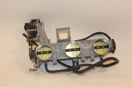 |
| The Speed Triple throttle bodies are one unit, and both the inlet and outlet are circular. |
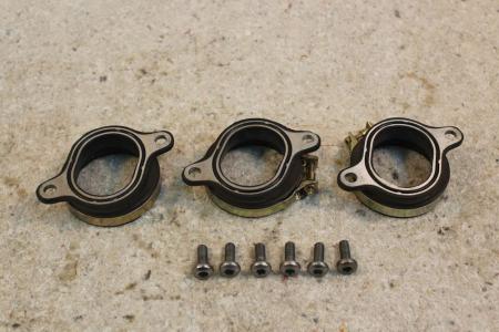 |
| The boots are oval on the engine manifold side, and circular on the TB side. |
With my trusty micrometer, I spent some time measuring the intake manifold gasket from the EZ and the TBs themselves, and determined that both the EZ and S3 intake ports are rect-oval shaped, with the ends being semicircles, and the long sides being straight.
- The EZ intake ports are 52mm long by 33mm wide
- The S3 intake ports are 45mm long by 35mm wide
- The S3 throttle bodies are 88mm center-to-center
- The EZ intake ports are 98mm center-to-center.
The EZ's intake ports are offset by ~46 mm right-to-left (the driver-side cylinders are rear of the passenger-side). That doesn't matter for this design, but if I were to build a single-piece manifold, I'd need to know it.
For this design, I'm going to build a short intake manifold, something like this:
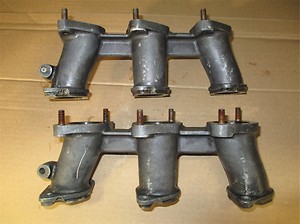 |
| 911 Weber intake runners made from cast aluminum |
It's simple, and will allow me to position the TBs where I need them, which is about 4" up from the intake port mating surface, and with the rearmost cylinder TB located about 2" forward of the intake port. I considered tilting the TBs to increase the runner length, but the alternator becomes an issue on the passenger side, and I'd really like to be able to make the manifold symmetrical to ease design and production.
I'm also going to make them out of composites. I don't have easy access to a 5-axis mill, nor the expertise to program one. I do, however, have a working knowledge of SketchUp and know where to have things 3D printed. Also, CF makes all the onlookers excited.
The next step, then, is to draw the footprints I'm working with in SketchUp. I start with a 3D model, but lay out the shape of the intake port in 2D. For the rect-oval shape, I lay out two circles with centers the correct distance, lay a rectangle over them, and delete the corners. The result is something like this:
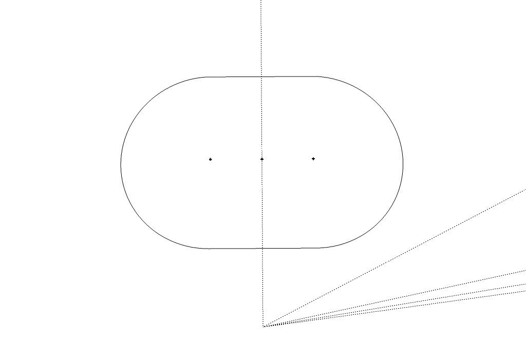 |
| The shape of an EZ30 intake port |
The guide points are for the centers of the circles (left/right) and the center of the overall shape. I then duplicated the shape, and laid three out on a plane according to the centers I measured earlier. The same process is used for the throttle body mating surfaces. I then arrange the two sets of outlines in 3D space, separating them by the height I want my manifold. In the next picture. I've added interior shapes in order to be able to make walls (more on that later), and drawn a Bezier curve between the center points. This curve defines the path that the intake manifold runners will follow. I adjusted the control points to balance keeping the inlets straight without having hard kinks in the runner. Here it is now:
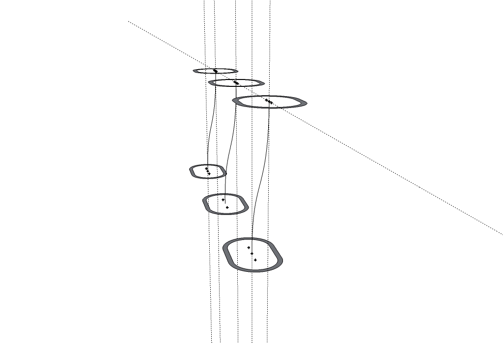 |
| Port outlines arranged in 3D space |
Because the port shapes have different dimensions, I had to find a way to draw a surface smoothly between them. In the CAD world, this is called "lofting", and there's a fantastically useful tool for SketchUp called Curviloft. Take careful note that I kept the centers aligned on a plane - that is, both faces "point" the same way. This was both for symmetry and because lofting in complex 3D ways is difficult. I could never get it to work quite right, and always had odd twisting effects introduced if I rotated them in order to, for example, orient the throttle bodies horizontally.
Once I've gotten the edges placed, I loft the faces of the walls, and use the push/pull tool to add a few mm of straight section. I'll slip the flanges over that. The result looks something like intake runners.
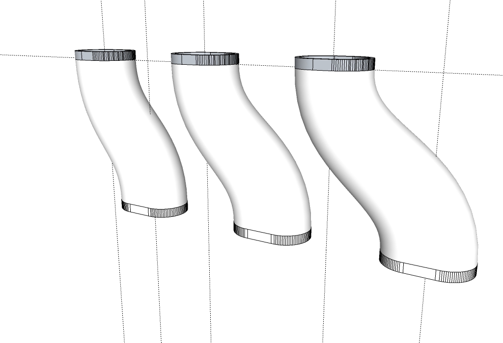 |
| Intake runner interior volume shapes. |
It's worth discussing now that I'm going to be 3D-printing this using the Ponoko service in white plaster. My intention is to use it as a plug for the interior volume of the intake runners, and lay up the manifold around them. Because 3D printing is really expensive, I've made the plug hollow - that's why there are 3mm "walls". The outside dimension is the one that matters here.
I've also added some details. Because the three runners are all different (each port is on a slightly different center, remember), they're each unique. Ponoko doesn't permit separate parts to be printed in a single job, and there's a $15 setup fee per job, so I've "bridged" the parts. The bridge will also help hold the parts in place while I prepare them later. I've added offset notches so I know where the center of the part is (for making a flanged mold), and marked the parts with letters just to I'm sure which runner is which. The final result is this:
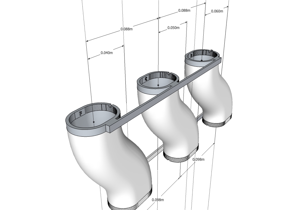 |
| The final plug CAD design, ready to print. |
Once I've got the runners printed, I'm probably going to fill them with something - silicone or urethane, perhaps - to make them solid.
So now that I've got my runner volumes mapped, I need to cut some flanges. That's easy! Using the FlightsOfIdeas SVG Outline plugin, I select the relevant edges and export. I then import the result into InkScape. The initial import looks like this:
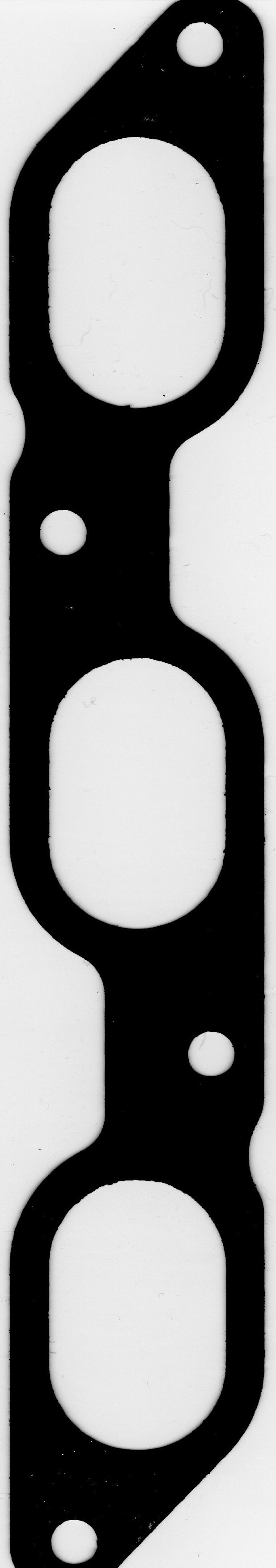
I then used my flatbed scanner to scan the intake manifold gasket:
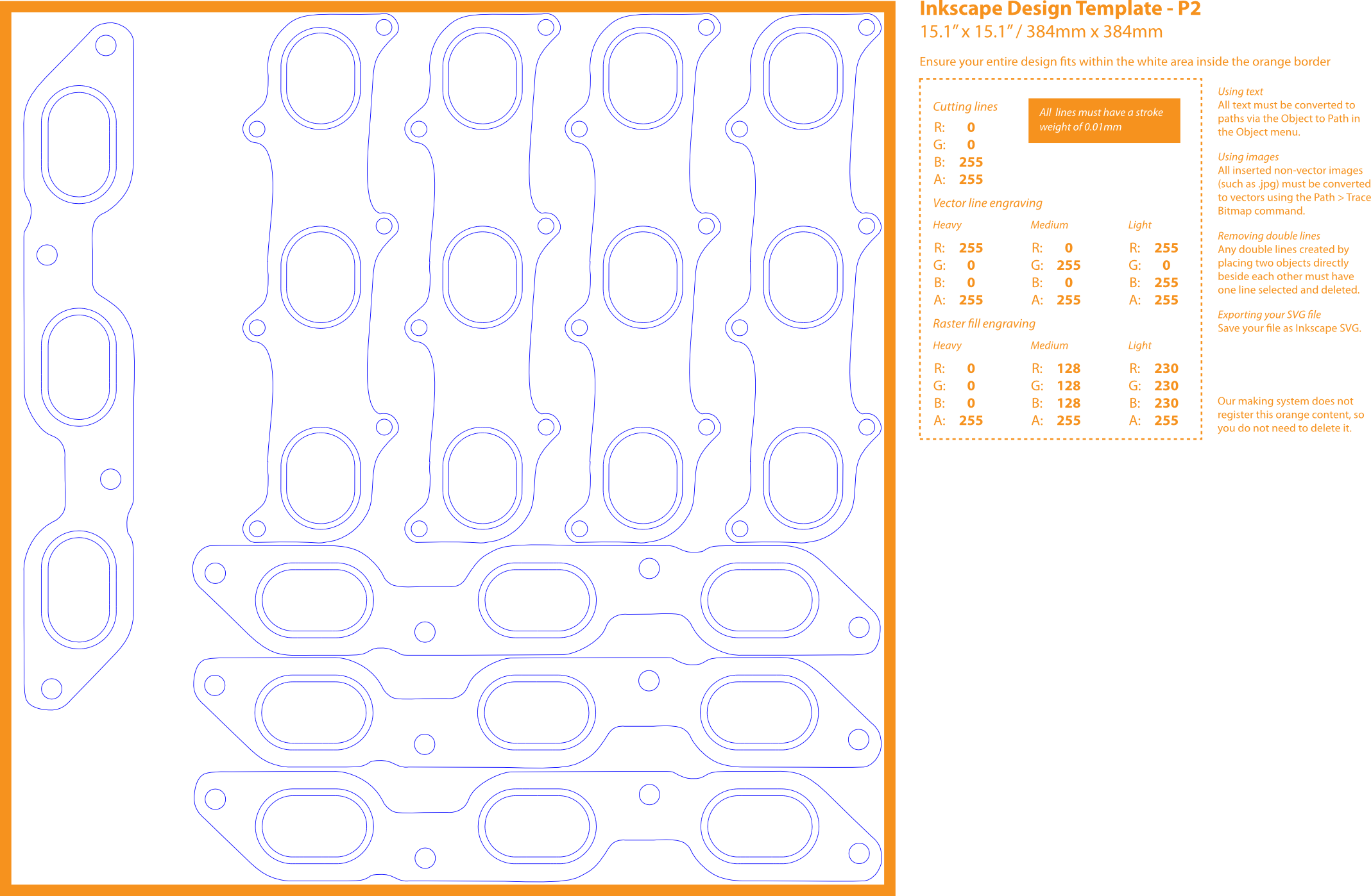
I then overlaid them to check the match. The error ended up being on the order of 1mm! That's within the fudge factor of the intake manifold gasket, in my opinion. Great news. With that, I traced the gasket in InkScape, and the repeated the process for the throttle body flange. With a little bit of further cutting and pasting, this is the result of putting the outlines in the Ponoko template:
The final cost for the parts from Ponoko was about $160. That's astoundingly cheap to go from measurement to physical widget. Now I wait until the print arrives and I can start prepping it for use as a plug.

No comments:
Post a Comment